
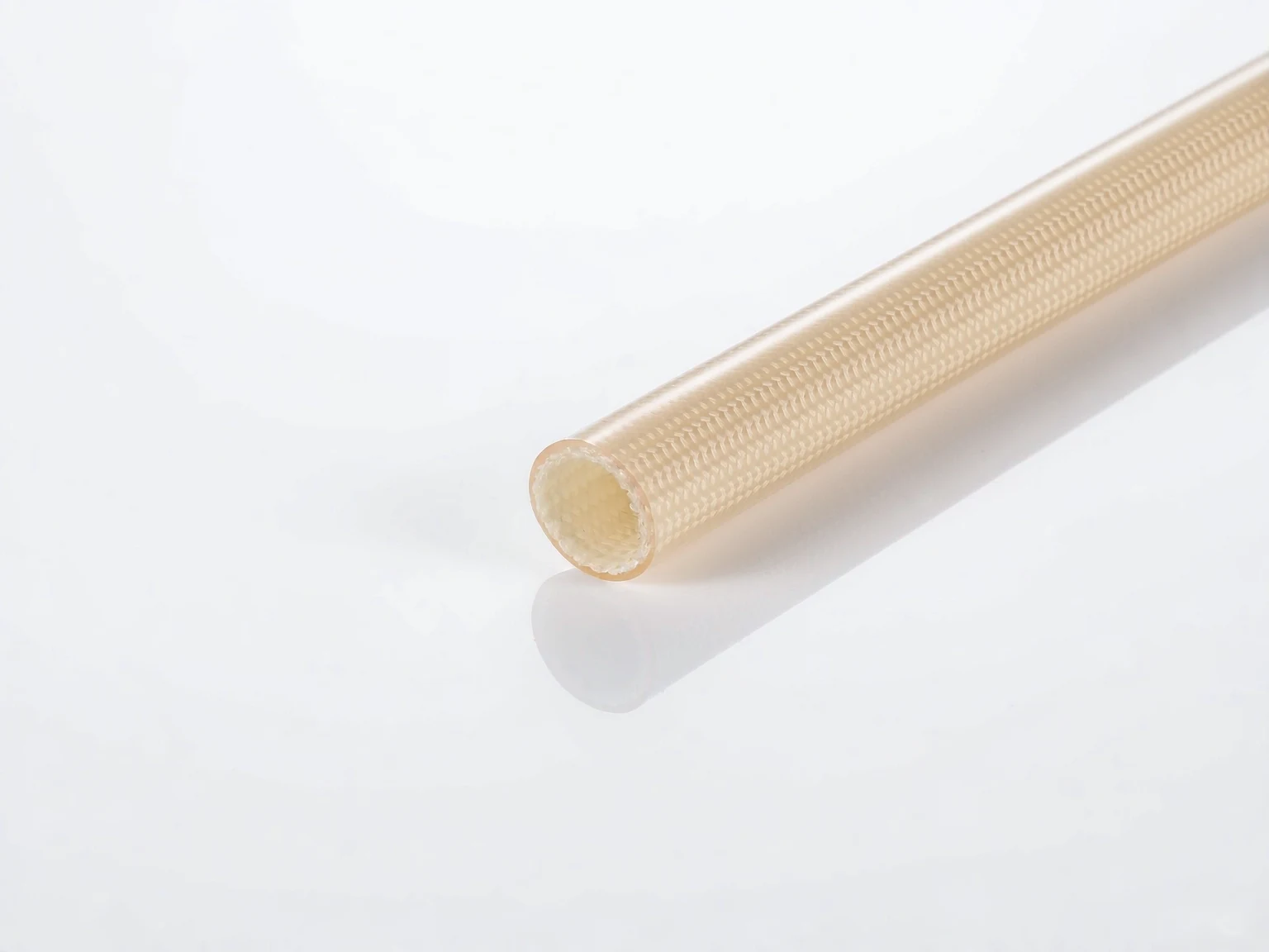
Silicone Resin
Balances heat resistance, dielectric performance and dimensional stability for transformer leads, power supplies and industrial insulation.
ENGINEERING GUIDE
A temperature number alone is not enough to qualify electrical fiberglass sleeving. Coating chemistry, continuous and peak exposure, dielectric requirements, bending, fluids and approval standards determine reliable service.
MATERIAL COMPARISON
Balances heat resistance, dielectric performance and dimensional stability for transformer leads, power supplies and industrial insulation.
Provides flexibility and high-temperature capability for motor leads, harness bends and vibration-prone assemblies.
Supports applications balancing cost, mechanical protection and moderate thermal requirements.
RATING CONTEXT
Published temperature classes are tied to defined tests. Real assemblies add conductor heating, ambient temperature, thermal cycling, fluids, bending and local hot spots.
Document continuous temperature, peak temperature and duration separately. If sleeving is part of the primary insulation system, confirm dielectric withstand and system requirements independently.
ENGINEERING DATA
The values below are an engineering screening framework for RFQ discussions, not a substitute for the current product datasheet or a witnessed qualification test. Confirm the final construction, wall build, colour and lot before release.
| Construction direction | Continuous design window | Short peak screening | Dielectric / voltage check | Approval direction | Typical fit |
|---|---|---|---|---|---|
| Acrylic-coated fiberglass | 155°C class | 165–180°C only when the assembly test supports it | Check insulation resistance, dielectric withstand and wall coverage on the finished part | Review the applicable UL 1441 style and file conditions | General harness routing, moderate heat and cost-sensitive builds |
| Silicone-resin fiberglass | 200°C class | 215–230°C for defined short exposure, subject to thermal cycling | Verify the project voltage, cut length, flaring and minimum wall after installation | Use the current WCW UL / CUL documentation where required | Motor leads, transformer leads and power modules |
| Silicone-rubber fiberglass | 200°C class with higher flexibility | Short peaks depend strongly on bend radius, compression and dwell time | Test the assembled lead rather than relying only on braid-level data | Confirm the required flame and chemical test package | Vibration, repeated bending and tight routing |
| High-temperature special construction | Project-specific; do not infer from the name | Set the peak profile before selecting the material | Run dielectric, abrasion and thermal-ageing checks on samples | Map the exact part to the requested UL, CQC or customer standard | Hot zones, heaters and special validation projects |
A temperature class is only one input. Conductor self-heating, ambient temperature, contact pressure, oil or coolant exposure and the adjacent insulation system can reduce the usable margin.
SELECTION METHOD
COMMON ERRORS
A 200°C label cannot compensate for a tight bend, poor coverage or a connector that transfers heat into the sleeve. Select margin from the measured assembly profile and verify the weakest location.
A short oven excursion and a temperature held for thousands of hours have different ageing effects. Put both values, plus dwell time and cycle count, on the RFQ instead of writing only “high temperature”.
Dielectric strength changes after cutting, expanding, flaring, crimping and exposing the braid to contamination. Test the finished lead with the actual conductor, terminal and neighbouring materials.
Nominal inner diameter is not enough. Measure minimum and maximum bundle diameter, installation force and post-installation movement. Add a retention or end-treatment plan when vibration is present.
Coolant, oil and cleaning agents can soften or embrittle a coating, while a flame class may depend on wall build and the exact colour. Request the relevant report and reproduce the exposure in sample validation.
WORKED EXAMPLE
Consider a motor lead routed beside an inverter housing. The first request says only “fiberglass sleeve, 200°C, UL required”. That request leaves too many decisions open: the measured conductor rise is unknown, the peak duration is missing, the sleeve may be primary or supplementary insulation, and the bend near the terminal is not described. A supplier can quote a nominal product, but the engineering team still cannot judge whether it will survive installation or service.
After measurement, the same request becomes actionable: 142°C continuous at the bundle, 188°C for 20 minutes during an overload event, 600 V working voltage, 8.4–9.1 mm bundle diameter, a 12 mm minimum bend radius, silicone oil splash, and a 2,000-hour thermal-cycle target. The drawing also shows a 35 mm flared section over the terminal and a requirement that no braid remain exposed after crimping. Those details point toward a flexible silicone-rubber or silicone-resin construction with controlled expansion, a defined cut length and an installation check at the flare.
The sample plan then has a clear pass/fail path: inspect the minimum wall and coverage, install five pieces with the production crimp, record pull or movement after vibration, cycle between ambient and the measured peak, apply the specified dielectric test, and inspect for cracking, whitening, delamination or exposed braid. If the sleeve passes electrically but creeps toward the terminal, the solution is not simply a higher temperature grade; it may require a different diameter, end treatment or routing restraint. This is why the heat curve, geometry and process belong in the first RFQ.
VALIDATION RECORD
A good approval package connects the drawing to evidence. Keep the material construction, nominal and tolerance dimensions, colour, lot, production process, test method, conditioning and acceptance criteria in one controlled record. Include photos of the installed sleeve before and after thermal cycling so movement, cracking, whitening, exposed braid or loss of coverage can be reviewed quickly.
For a motor or transformer lead, the minimum practical package normally includes dimensional inspection, installation confirmation, dielectric withstand, insulation resistance, thermal ageing or cycling, bend or vibration exposure, and a visual check of every termination. For a liquid-cooling or fluid-adjacent harness, add the project fluid, concentration, temperature and immersion or splash duration. If the part is safety-related, align the test plan with the customer standard before samples are built.
WCW can review a drawing, imported part number, sample or failed test report and return a recommendation with the information still missing. The fastest RFQ includes the heat curve, voltage, bundle diameter, target approval, fluid list, estimated annual demand and required sample date.
RFQ CHECKLIST
VIDEO GUIDE
See a quick application view, then use the comparison and checklist on this page to define the correct coating system and validation conditions.
View all technical videosFAQ
No. Compare coating, dimensions, wall build, dielectric strength, flexibility, flammability and aging. A same-class construction can still behave differently after cutting, expansion or fluid exposure.
Include installation, bending, thermal aging, dielectric and end-use environmental tests. Use the production tool, terminal and operator method whenever possible.
Not automatically. Leave a project margin for measurement uncertainty, conductor heating, hot spots and ageing. Define the continuous value and peak dwell separately, then confirm with a representative cycle test.
Send the application, heat curve, voltage, bundle diameter, wall or clearance limits, bend radius, fluids, approval target, sample quantity and annual demand. A drawing or imported sample is helpful but not mandatory.
ENGINEERING SUPPORT
Include application, continuous and peak temperature, size, voltage, approvals and estimated demand.